Assessing your optical link budget for a successful embedded WDM network
Many people looking to build an embedded WDM network will use the distance specification of the transceiver and the distance of the fiber as the key criteria for designing the network. This is a risky way to go. Under ideal circumstances, a DWDM ZR transceiver can theoretically span 80km and a CWDM ZR 80km. Yet this distance specification of an optical transceiver is only a guide. In reality, disturbances usually occur along the way from the transmitting to the receiving end of the fiber, such as mux/demux losses, fiber losses and patch losses.
Link loss: A long and winding road along the fiber expressway
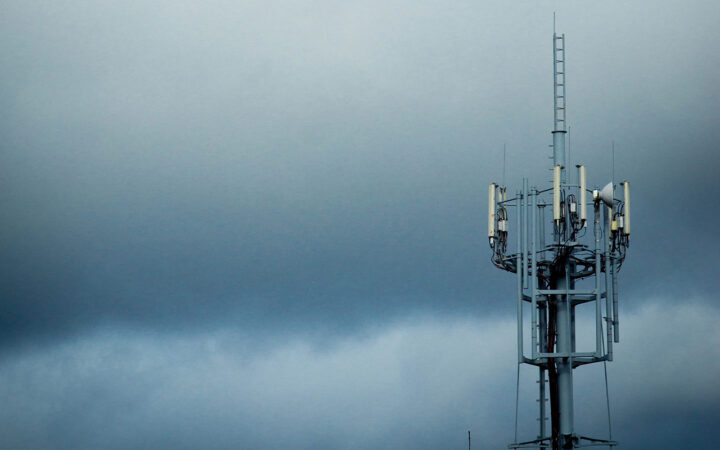
Just like with roads, there’s a tremendous difference between the ideal scenario and the real-world conditions in which the elements actually operate. Roads can be long, short, go uphill and down, around tight bends, and lead to diversions and blocks. The same applies to fiber cables: they’re never in a straight line with the ideal conditions we’d like to imagine. A brand-new fiber with low losses can allow longer transmission distances than an older fiber. Older fibers may have splices along the route that result in higher losses, making the conditions less than ideal. That’s why you must know the conditions of the fiber and other equipment involved in order to specify and build a successful optical network.

As an example, let’s assume the vehicle starts with a full tank of fuel enough for 80km as the crow flies. If the weather is nice and the road isn’t too bendy (no pot holes and no long uphill sections), then the fuel should be enough to get the vehicle the full 80km.
Now, what happens if we set off on another 80km journey, but this time we drive uphill in a horrendous gale, along badly maintained roads, and need to stop and restart due to all types of external conditions outside of our control? Chances are we won’t make the 80km.
The power of a transceiver is usually described as the transceiver power budget. We can compare this to the fuel tank in the car. The bigger the tank, the more power budget, and the farther the light can travel in the fiber. Still, just as the size of the tank alone will not define how far the car can travel, the same goes for the transceiver. The distance specification of the transceiver is by no means a guarantee for the performance of the signal in reality. We’ve got to consider external conditions, so we need to compare the transceiver power budget to the hinders along the way.
Calculating the optical link budget
When designing a complete embedded WDM solution, the most important task is calculating what is commonly referred to as the optical link budget. It starts off with the transceiver power budget but also considers all the potential losses from the transmitter side, through the multiplexers, patch panels and dark fiber to the receiver side of the system. Simply put, the link budget determines whether the selected transceiver will be powerful enough to transmit the signal across the fiber despite the losses on the way.
Link budget calculation
+ Transceiver power budget
– Mux/demux losses
– Fiber losses
– Any patch panel and connector losses
= Total link budget
If the result of the power budget calculation is positive, the signal will be carried through and a successful implementation is possible. If the result is negative, i.e. if the losses exceed the transceiver power budget, the signal will not reach its end destination. (In this second scenario amplifiers could be used, something we will cover in another article.)

System is within tolerance, link will work
Higher fiber losses, system is out of tolerance
By calculating the link budget, we can find the optimal parameters of the transmitting and receiving devices to ensure proper signal transmission. A link budget assessment enables us to design the system so that it meets its requirements without being overdesigned at extra cost.
Optical time-domain reflectometer measures the state of the fiber
To begin the link budget assessment, we need to determine the condition of the fiber. To do this, we can obtain the optical time-domain reflectometer (OTDR) readings for the fiber, which are usually available from the fiber provider if the fiber is being leased.
An OTDR is an instrument used to characterize the state of the fiber. It injects a series of optical pulses into the fiber to establish any losses or reflections. A loss means that light leaks out of the path and the signal strength becomes degraded. Reflection occurs when light is reflected back in the same direction it came from. Connectors, tight-bend radiuses and splice joints can all contribute to a fiber with higher losses than desired. These return pulses are measured and plotted as a function of fiber length.
The attenuation of the fiber is measured in decibels (dB) per kilometer, indicating how much the signal attenuates and degrades per distance it travels. For estimation purposes, a typical standard value used to estimate the losses through a fiber is a loss of 0.25dB per km. The OTDR results will give the exact measurements based on the current state of the fiber, and the resulting graph shows the attenuation of the fiber as a function of distance.
Examples of optical link budget estimates
Once the state of the fiber is known from the OTDR results, we can complete our link budget assessment using the formula above.
Example 1:
Let’s say that we want to transmit 10G traffic, using a SFP+ ZR transceiver. The power budget is 23dB. Now, let’s assume that we also require a 16 channel mux/demux with a loss of 4.5dB. (The loss of network components is specified for the equipment.) The loss in a 60 km long fiber at is 0.25dB/km. The total loss in the fiber will be 0.25dB/km x 60 = 15dB.
Link budget calculation
Transceiver power budget: 23dB
Fiber losses, 60km at 0.25dB/km: 15dB
Mux/Demux losses: 4.5dB
Various patch/splicing losses (margin): 1.0dB
Total system link loss: 20.5dB
RESULT: 2.5 dB
23dB -20.5dB in losses leaves 2.5dB of additional system margin, meaning the design is within spec and will work.
Example 2:
Now let’s assume the loss in the fiber is 0.4dB/km (instead of 0.25dB) and make the calculation again.
Link budget calculation
Transceiver power budget: 23dB
Fiber losses, 60km at 0.4dB/km: 24dB
Mux/Demux losses: 4.5dB
Various patch/splicing losses (margin): 1.0dB
Total system link loss: 29.5dB
RESULT: -6.5 dB
If the same ZR transceiver would have been chosen, then the system would not work.

Related articles

What is a SAN ( Storage Area Network) and how does it protect mission-critical workloads?

What is Fibre Channel used for?